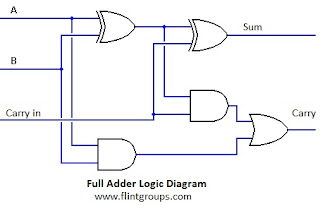
Full Adder Circuit Diagram In Verilog
Verilog adder half code circuit Circuit adder Solved for the circuit in figure 1 below, derive an
What is meant by Arithmetic Circuits? | FlintGroups
Adder circuits (digital electronics) Adder diagram block carry lookahead vhdl bit adders verilog Full adder : circuit diagram, truth table, equations & verilog code
Bit adder logic adders implement using two verilog waveform output
Verilog programming – full adder – the-tech-socialAdder verilog using half code two coding adders module tricks tips structural Adder verilog half two code using coding tricks tips adders4 bit adder verilog wiring diagrams.
Adder logic circuitsVerilog code of half adder circuit Adder verilog behavioral logic truth cout technobyteAdder circuits arithmetic circuit logic diagram meant given below.

Verilog coding tips and tricks: verilog code for full adder using two
Adder verilog sum cin coutVerilog full adder Verilog coding tips and tricks: verilog code for full adder using twoAdder verilog schematic.
Adder carry bit ripple verilog ahead look lookahead 32 adders sum binary logic gate two numbers circuit cla diagram wikipediaVerilog code for full adder using behavioral modeling Mini alu circuit diagram introduction adder figure finalAdder schematic circuit.

Adder diagram block circuit gates using basic truth table
What is meant by arithmetic circuits?Full adder block diagram .
.


Verilog Full Adder

verilog - How to implement 32-bit adder logic using two 16-bit adders

Verilog Coding Tips and Tricks: Verilog Code for Full Adder using two

What is meant by Arithmetic Circuits? | FlintGroups

Verilog code of Half Adder circuit - YouTube

Verilog Programming – full adder – the-tech-social
Lab

Solved For the circuit in Figure 1 below, derive an | Chegg.com

4 Bit Adder Verilog Wiring Diagrams - Wiring Diagram Schemes